
Punching, Cropping and Shearing Clearances: A Practical Guide for Tool Design
Correct clearance between the cutting components of a tool is fundamental to achieving a clean cut, controlling cutting force and maintaining reasonable tool life.
There is no single fixed clearance that is suitable for every material thickness and every cutting operation. Clearance is normally calculated as a percentage of the material thickness, with the percentage adjusted according to the material being processed and the required cut quality.
This guide covers three common operations:
- Punching – producing a hole or profile through the material.
- Cropping or notching – removing material from the edge of a component.
- Shearing – cutting material between an upper and lower shearing tool.
1. Punching
Punching is not limited to round holes. The same basic tooling principle applies to a wide variety of punched profiles, including:
- Round holes
- Square holes
- Rectangular holes
- Slots
- Obround profiles
- Keyways
- Custom or irregular profiles
In a conventional punching operation, the punch defines the size and shape of the finished hole or profile.
The die opening must therefore be larger than the punch by the required clearance on each cutting side.
For a round hole, the clearance is added radially around the punch. Therefore, the die diameter is increased by twice the clearance.
For square, rectangular, slotted or irregular profiles, the same principle applies: the die profile is offset outward from the punch profile by the required clearance on each cutting edge.

Round die diameter = Punch diameter + (2 × clearance per side)
Non-round profiles = Die profile offset outward by the clearance on each cutting edge
Example: 6 mm Mild Steel with an 18 mm Hole
Assume a punching clearance of 6.5% of material thickness per side.
6 mm × 0.065 = 0.39 mm clearance per side
Required finished hole = Ø18.00 mm
Punch diameter = Ø18.00 mm
Die internal diameter = 18.00 + (2 × 0.39)
Die internal diameter = Ø18.78 mm
The clearance is applied radially. Therefore, when calculating the diameter of the die opening, the clearance must be added twice.
2. Cropping and Notching
Cropping uses the same basic shearing principle as punching, but instead of producing an enclosed hole, the tool removes material from the edge of the workpiece.
Where the remaining workpiece is the finished component and the cropped section is waste, the lower die defines the finished cropped radius or profile.
The upper punch must therefore accommodate the required cutting clearance relative to the die profile.
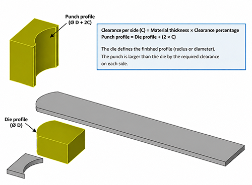
Punch radius = Die radius + clearance per side
Equivalent punch diameter = Die diameter + (2 × clearance per side)
Example: 6 mm Mild Steel with an R35 Crop
Assume a cropping clearance of 7.5% of material thickness per side.
6 mm × 0.075 = 0.45 mm clearance per side
Required finished profile = R35.00 mm
Die profile = R35.00 mm
Punch profile = 35.00 + 0.45
Punch profile = R35.45 mm
Expressed as a complete diameter:
Die profile = Ø70.00 mm
Punch profile = 70.00 + (2 × 0.45)
Punch profile = Ø70.90 mm
The important distinction from conventional hole punching is which tool controls the finished component. In this cropping arrangement, the die defines the required finished profile and the punch incorporates the necessary clearance.
3. Shearing
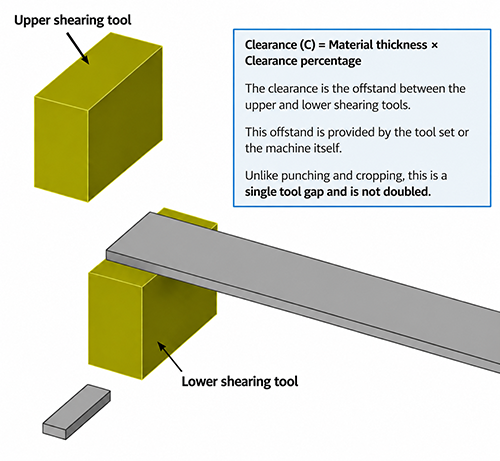
In shearing, the clearance is the offstand or gap between the cutting edge of the upper shearing tool and the cutting edge of the lower shearing tool.
This clearance is provided by the tool set or by adjustment of the machine itself. Unlike the diameter calculation for punching and cropping tools, the shearing clearance represents a single tool gap and is therefore not doubled.
Example: 6 mm Mild Steel
Using a nominal shearing clearance of 7% of material thickness:
6 mm × 0.07 = 0.42 mm
The required offstand between the upper and lower shearing tools would therefore be approximately 0.42 mm.
Typical Clearance Ranges
The following figures provide practical starting points for general-purpose tooling. All percentages are based on material thickness.
| Material | Punching Per Side |
Cropping Per Side |
Shearing Tool Gap |
|---|---|---|---|
| Mild Steel | 5–8% | 5–10% | 5–8% |
| Stainless Steel | 8–12% | 8–12% | 7–12% |
| Aluminium / Soft Non-Ferrous | 3–6% | 4–7% | 3–6% |
Choosing the Correct Clearance Within the Range
The optimum clearance depends on more than material thickness alone. Material strength, hardness, ductility, required edge quality, tool construction and production requirements all influence the final selection.
Using the Lower End of the Clearance Range
- Softer material.
- Better cut-edge quality is required.
- Greater dimensional accuracy is required.
- Material is relatively thin.
- Higher cutting force is acceptable.
- The tooling is rigid and accurately aligned.
Using the Higher End of the Clearance Range
- Harder or higher-strength material.
- Material is relatively thick.
- Lower cutting force is desirable.
- Tool life is a higher priority than maximum edge quality.
- Some additional rollover or burr is acceptable.
The Effect of Clearance
Reducing the clearance generally increases the proportion of smooth burnished material at the cut edge and can improve dimensional accuracy. However, cutting force increases and excessive reduction in clearance can increase tool wear, galling and the risk of damage to the punch or die.
Increasing the clearance generally reduces cutting force and can improve tool life, but excessive clearance increases rollover, fracture angle, taper and burr formation.
The objective is therefore not to use the smallest possible clearance, but to select a clearance that provides an appropriate balance between cut quality, cutting force, dimensional accuracy and tool life.
General-Purpose Starting Points
Where a specific clearance has not already been established through tooling experience, material specifications or testing, the following values provide useful general-purpose starting points:
| Operation | General Starting Clearance |
|---|---|
| Punching | Approximately 7% of material thickness per side |
| Cropping | Approximately 8% of material thickness per side |
| Shearing | Approximately 7% of material thickness as the gap between the upper and lower shearing tools |
Summary
Clearance should normally be related to the material thickness and material being cut, rather than using one fixed clearance for every application.
For punching, the punch defines the finished hole or profile and the die is provided with clearance around its cutting edges. For a circular hole, this means that the die diameter increases by twice the specified clearance per side.
For cropping or notching where the remaining workpiece is the finished component, the die defines the finished cropped profile and the upper punch incorporates the required clearance.
For shearing, the specified clearance is the offstand or gap between the upper and lower shearing tools. This is provided by the tool set or machine adjustment and is not doubled.
These figures should be regarded as practical starting values rather than absolute rules. Final clearance should take account of the exact material grade, material thickness, required component quality, production volume, tool design, tool alignment and condition of the press.
The Workshop Press Company supplies press tooling, accessories and engineered solutions for punching, cropping, shearing and other press applications.View our press accessories and tooling →